We use cookies to make your experience better. To comply with the new e-Privacy directive, we need to ask for your consent to set the cookies. Learn more.
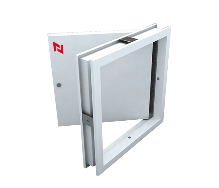


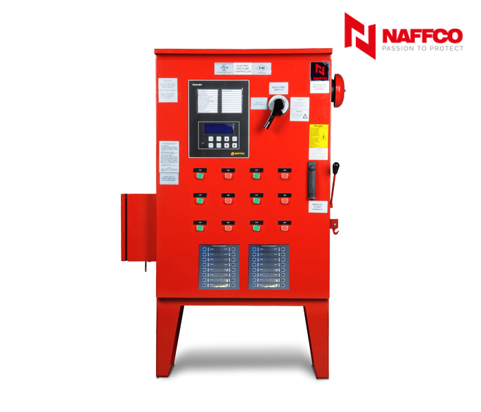


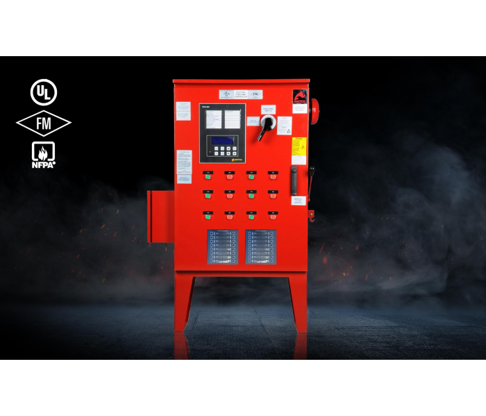
Starter Panels
- Listed by underwriter's laboratories in accordance with UL218.
- Complying with NFPA 20 and NFPA 70 standards NEMA.
- Approved as per FM standard 1321 / 1323.
- High quality ul listed or ul recognized components are used.
- Enclosures for various condition as per NEMA standard.
Contact Us to Purchase
Features
|
POWER RATING |
15 - 400 HP |
|
TYPE |
DOL, Y-DELTA, SOFT STARTER, VFD |
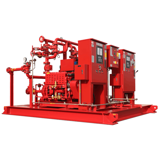
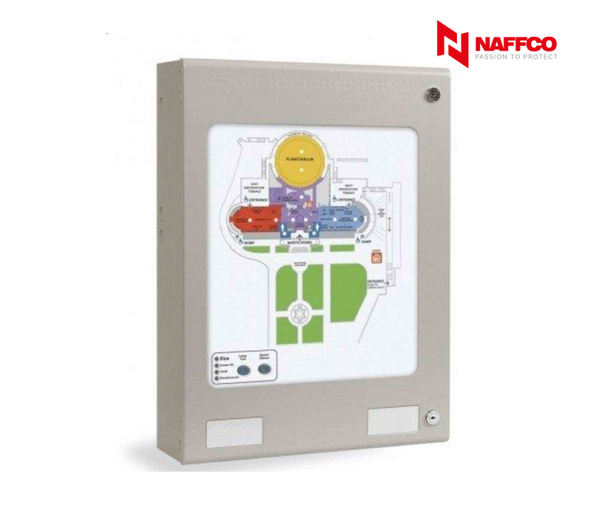
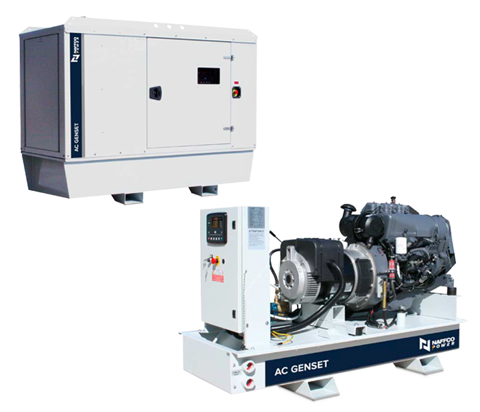
Starter Panel & Fire:
Designed and manufactured to the highest standards in a quality-controlled environment and with UL & FM approvals, the NAFFCO/SHIELD panel offers outstanding value and performance for all Smoke Management installations. The Control Panels are manufactured to the requirements of UL 864.
Specifications
PRODUCT
- Starter panels shall be manufactured and assembled as per local authority requirements and standards.
- All motors shall be provided with heavy-duty contactor-type motor fuse less starters selected for coordination type 2 generally complying with the following and protected through circuit breaker.
- up to 5KW direct on line starting.
- From 5KW to 25KW Star Delta starting or VFD.
- 25KW and above reduced voltage electronic soft starters or VFD.
- Each starter panel shall be provided with a main incoming circuit breaker capable of carrying the full load current.
- Each starter shall comprise as a minimum:
- One triple pole thermal over current relay incorporating over current, phase sequence and single-phase protection with adjustable trip settings.
- One control circuit MCB or fuse and one copper link.
- Each starter shall be fitted with one set of local start/stop push buttons and hand/off/auto selector switch as required.
- Where more than one motor with a duty/standby or duty/backup functions used, the starter control wiring shall be arranged to automatically change duty upon the fault tripping of the selected motor. A duty/standby or sequence selector switch shall be provided. Where multiple motors with duty only, the starter panel control wiring shall be arranged separately to avoid tripping of all motors together.
- Each starter shall be fitted with LED lamps indicating:
- RUN condition (green)
- TRIP condition (red)
- Supply voltage indications for each phase
Each starter control wiring shall include control terminal and control relays as necessary to achieve any interlocking specified elsewhere or to achieve any control or monitoring through the other systems such as BMS and Fire Alarm services.
- Adjustable time delay devices be provided for Star Delta Starters.
- Proper earth leakage protection to be provided as per local authority standards.
- All Star Delta starter shall be provided with mechanical or electrical interlocks for star delta contactor assembled to prevent short circuiting.
- Starters for three phase motors to be magnetic type to automatically disconnect motor from power supply in case of supply failure, excessive voltage drops, overcurrent and lack of balance in phases.
- Overload trips to be provided for three phases.
- Control voltage for starters and control circuits shall be taken from the same power supply source of control panel.
VFD (VARIABLE FREQUENCY DRIVE)
Variable speed drive controller, listed and labelled as a complete unit and arranged to provide soft starting and modulated speeds of a recognized standard induction motor by adjusting output voltage and frequency.
EXECUTION
- Select features of each motor controller to coordinate with ratings and characteristics of supply circuit and motor; required control sequence; duty cycle of motor, drive, and load; and configuration of pilot device and control circuit affecting controller functions.
- Select the appropriate electrical ratings of controllers to suit the motors controlled.
- Push-Button Stations: In covers of magnetic controllers for manually started motors where indicated, start contact connected in parallel with sealing auxiliary contact for low- voltage protection
- Hand-Off-Automatic Selector Switches: In covers of manual and magnetic controllers of motors
started and stopped by automatic controls or interlocks with other equipment.
INSTALLATION
- Install motor-control centres according to accepted and manufacturer's written instructions.
- Anchor each motor-control centre assembly to steel-channel sills arranged and size according to manufacturer's written instructions. Attach by tack welding or bolting. Level and grout sills flush with motor-control centre mounting surface.
- Install motor-control centres on concrete housekeeping bases. D. Fuses: Install fuses in each fusible switch as indicated.
- Power and Control Wiring: Run in separate conduits unless otherwise specified. F. Rigid conduits shall not terminate in nor be fastened to a motor frame or base.
- Flexible conduits to be used at motor connections. Allow sufficient slack to permit motor to slide over adjustable length of motor base.
- Flexible Conduits: Length and radius to be sufficient to permit bending of feeder cables without damage to conductor or its insulation.
- Flexible Conduits: Do not use in place of rigid conduits except at motor connections, unless otherwise specified.
- Support conduit with conduit supports in an adequate approved manner.
- Conduits shall not cross pipe or vent shafts, ducts or openings. They shall be run a minimum 100 mm away from pipes of non-electrical services.
- Conduits: Install so that moisture can drain to lowest point. Provide screw plug at all low points for draining.
CONNECTIONS
Tighten properly the control and monitor terminals, electrical connection terminals etc.
CONTROL WIRING INSTALLATION
- Bundle, train, and support wiring in enclosures. Protect circuits with high rupturing capacity fuses or circuit breakers. Auxiliary supply for controls other than from main power circuit, to be effectively isolated by auxiliary contacts on main isolator.
- Connect hand-off-automatic switch and other automatic control devices according to an indicated wiring diagram or one that is manufacturer approved, where available.
Resources
|
Catalog |